文章目录
- 1. 双目检测
- 1.1 调用相机
- 1.2 分割画面
- 2. 双目标定
- 2.1 相机标定
- 2.2 获取参数
- 3. 双目测距
- 3.1 立体校正
- 3.1.1 校正目的
- 3.1.2 校正方法
- 3.1.2 相关代码
- 3.2 立体匹配和视差计算
- 3.3 深度计算
- 3.4 注意事项
- 4. 完整代码
代码打包下载:
链接1:https://download.csdn.net/download/qq_45077760/87680186
链接2:https://github.com/up-up-up-up/Binocular-ranging(GitHub)
本文是实现某一个像素点的测距,想用yolov5实现测距的,请移步👉这篇文章
1. 双目检测
1.1 调用相机
打开相机,测试双目相机两个画面是否正常显示,也可进行棋盘格拍照
import cv2
cap =cv2.VideoCapture(1)    # 打开相机,根据设备而定,一般是0或1
cap.set(cv2.CAP_PROP_FRAME_WIDTH, 2560)     # 设置相机分辨率 2560x720
cap.set(cv2.CAP_PROP_FRAME_HEIGHT, 720)
fourcc = cv2.VideoWriter_fourcc(*'XVID')    # 保存为avi格式
out = cv2.VideoWriter('myvideo.avi',fourcc, 20.0,(2560,720))
i= 0
while True:
    ret, frame = cap.read()
    if not ret:
        print("Can't receive frame (stream end?). Exiting ...")
        break
    out.write(frame)
    cv2.imshow('camera',frame)
    key = cv2.waitKey(1)
    if  key == ord('q') or key == 27:      # 按下q退出程序并保存视频
        break
    if key == ord("w"):                 # 按下w保存图片
    cv2.imwrite("./%d.png" % i, frame)  # 设置拍摄照片的保存路径
    print("Save images %d succeed!" % i)
    i += 1
cap.release()
out.release()
cv2.destroyAllWindows()
1.2 分割画面
同理把这个代码稍作修改,可以实现拍照功能,由于我这里是zed 2i相机,自带的有sdk,直接调用的api进行拍照,拍照后需要对双目画面进行分割:
from PIL import Image
import os

path = 'C:/Users/hp/Desktop/1'  # 文件目录
# path这个目录处理完之后需要手动更改
path_list = os.listdir(path)
print(path_list)

for i in path_list:  # 截左半张图片
    a = open(os.path.join(path, i), 'rb')
    img = Image.open(a)
    w = img.width  # 图片的宽
    h = img.height  # 图片的高
    print('正在处理图片', i, '宽', w, '长', h)

    box = (0, 0, w * 0.5, h)  # box元组内分别是 所处理图片中想要截取的部分的 左上角和右下角的坐标
    img = img.crop(box)
    print('正在截取左半张图...')
    img.save('L' + i)  # 这里需要对截出的图加一个字母进行标识,防止名称相同导致覆盖
    print('L-', i, '保存成功')

for i in path_list:  # 截取右半张图片
    a = open(os.path.join(path, i), 'rb')
    img = Image.open(a)
    w = img.width  # 图片的宽
    h = img.height  # 图片的高
    print('正在处理图片', i, '宽', w, '长', h)

    box = (w * 0.5, 0, w, h)
    img = img.crop(box)
    print('正在截取右半张图...')
    img.save('R' + i)
    print('R-', i, '保存成功')

print("'{}'目录下所有图片已经保存到本文件目录下。".format(path))
2. 双目标定
2.1 相机标定
打开Matlab 上方的工具栏APP,找到图像处理和计算机视觉下的Stereo Camera Calibration工具,打开并将分割后的图片导入
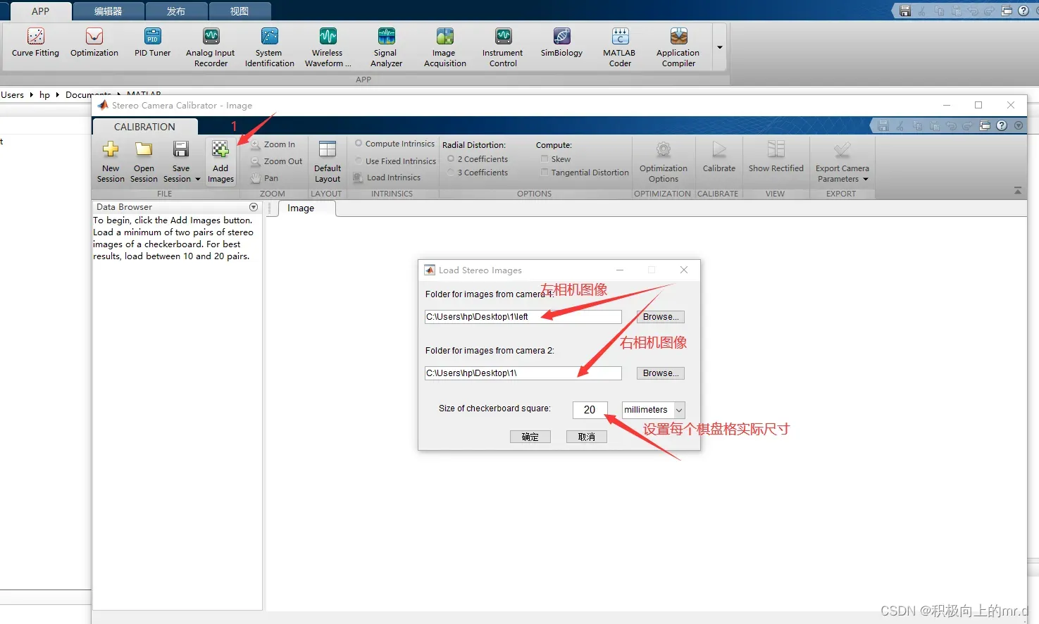
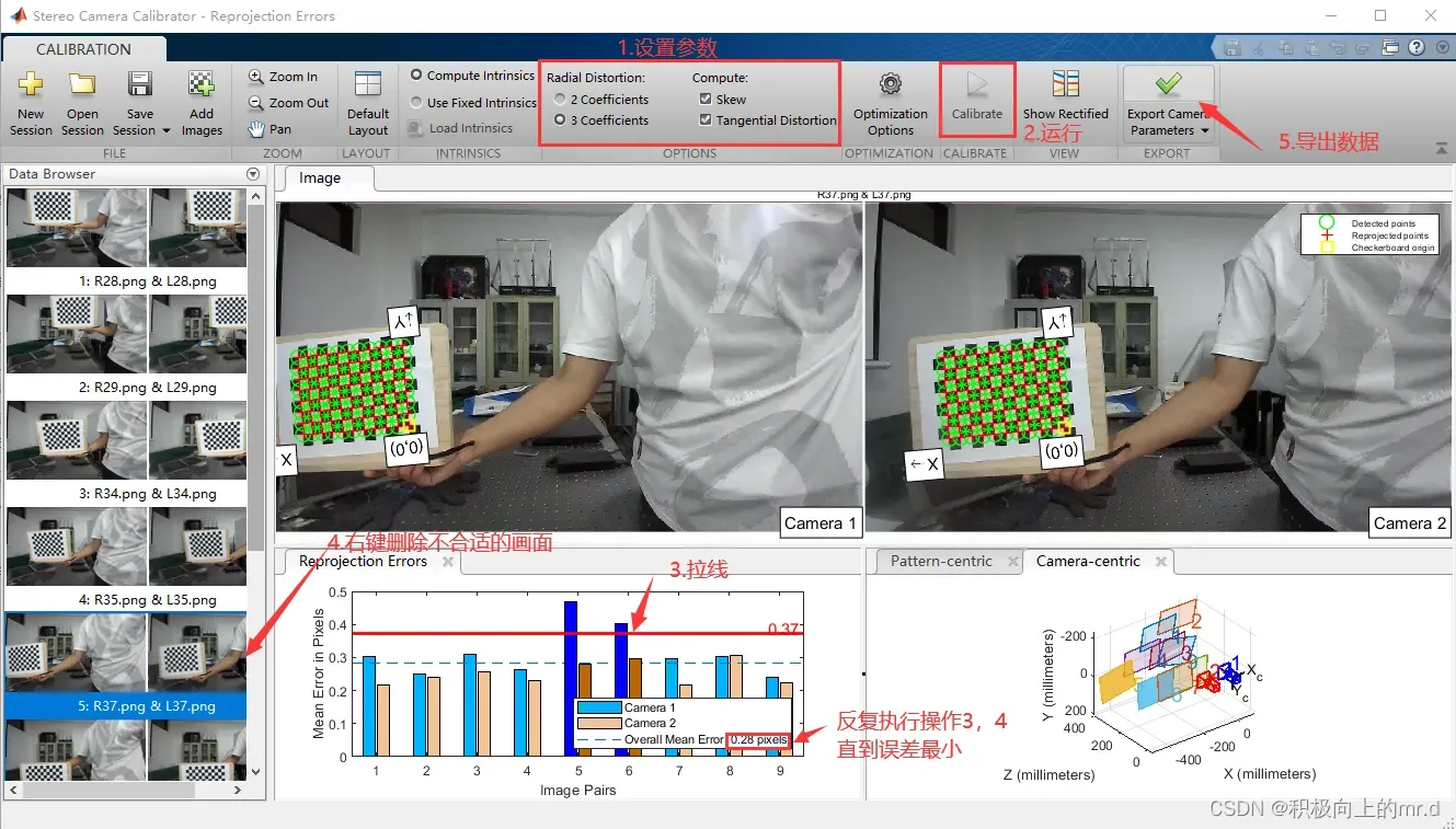
设置参数,对于一般的相机选择2 Coefficients选项即可,对于大视场相机则选择3 Coefficients选项。拉线删除误差较大的画面:
2.2 获取参数
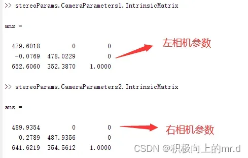
在matlab控制台分别输入 stereoParams.CameraParameters1.IntrinsicMatrix 和stereoParams.CameraParameters2.IntrinsicMatrix 获得左右相机的参数,下边填写时请注意进行矩阵的转置
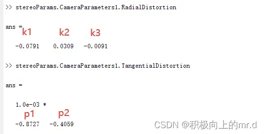
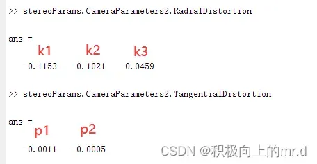
为了获取左相机的畸变系数:[k1, k2, p1, p2, k3],我们需要分别输入stereoParams.CameraParameters1.RadialDistortion 和 stereoParams.CameraParameters1.TangentialDistortion
同理分别输入 stereoParams.CameraParameters2.RadialDistortion 和 stereoParams.CameraParameters2.TangentialDistortion 获取右相机的畸变系数:[k1, k2, p1, p2, k3]
分别输入 stereoParams.RotationOfCamera2 和 stereoParams 来获取双目的旋转矩阵和平移矩阵
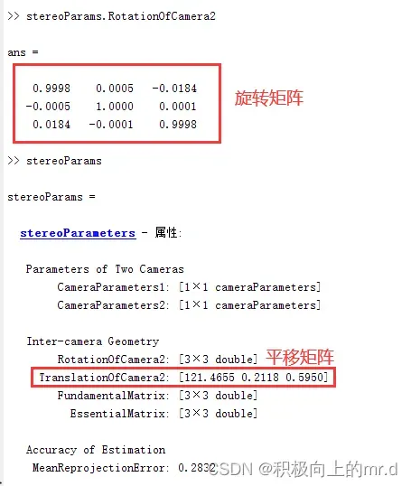
将以上参数填写进stereoconfig.py文件里,注意转置
import numpy as np

# 双目相机参数
class stereoCamera(object):
    def __init__(self):
        # 左相机内参
        self.cam_matrix_left = np.array([   [479.6018,   -0.0769,  652.6060],
                                            [       0,  478.0229,  352.3870],
                                            [       0,         0,         1]
                                        ])
        # 右相机内参
        self.cam_matrix_right = np.array([  [489.9354,   0.2789,  641.6219],
                                            [       0,  487.9356,  354.5612],
                                            [       0,         0,         1]
                                        ])

        # 左右相机畸变系数:[k1, k2, p1, p2, k3]
        self.distortion_l = np.array([[-0.0791, 0.0309, -0.0009, -0.0004, -0.0091]])
        self.distortion_r = np.array([[-0.1153, 0.1021, -0.0011,  -0.0005,  -0.0459]])

        # 旋转矩阵
        self.R = np.array([ [1.0000,  0.0005, -0.0184],
                            [-0.0005,  1.0000, 0.0001],
                            [ 0.0184,  -0.0001,  1.0000]
                            ])
        # 平移矩阵
        self.T = np.array([[121.4655], [0.2118], [0.5950]])
        # 焦距
        self.focal_length = 749.402 # 默认值,一般取立体校正后的重投影矩阵Q中的 Q[2,3]
        # 基线距离
        self.baseline = 121.4655 # 单位:mm, 为平移向量的第一个参数(取绝对值)
3. 双目测距
测距代码这一块参考这篇博文,将其中的open3d删除,以最简洁的方式展示出来,大致步骤:
双目标定 > 立体校正(含消除畸变) > 立体匹配 > 视差计算 > 深度计算(3D坐标)计算
3.1 立体校正
3.1.1 校正目的
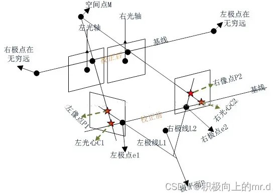
立体校正利用双目标定的内外参数(焦距、成像原点、畸变系数)和双目相对位置关系(旋转矩阵和平移向量),分别对左右视图进行消除畸变和行对准,使得左右视图的成像原点坐标一致、两摄像头光轴平行、左右成像平面共面、对极线行对齐。
校正前的左右相机的光心并不是平行的,两个光心的连线就叫基线,像平面与基线的交点就是极点,像点与极点所在的直线就是极线,左右极线与基线构成的平面就是空间点对应的极平面。
校正后,极点在无穷远处,两个相机的光轴平行。像点在左右图像上的高度一致。这也就是极线校正的目标。校正后做后续的立体匹配时,只需在同一行上搜索左右像平面的匹配点即可,能使效率大大提高。
3.1.2 校正方法
实验利用OpenCV中的stereoRectify()函数实现立体校正,stereoRectify()函数内部采用的是Bouguet的极线校正算法,Bouguet算法步骤:
1、将右图像平面相对于左图像平面的旋转矩阵分解成两个矩阵Rl和Rr,叫做左右相机的合成旋转矩阵
2、将左右相机各旋转一半,使得左右相机的光轴平行。此时左右相机的成像面达到平行,但是基线与成像平面不平行
3、构造变换矩阵Rrect使得基线与成像平面平行。构造的方法是通过右相机相对于左相机的偏移矩阵T完成的
4、通过合成旋转矩阵与变换矩阵相乘获得左右相机的整体旋转矩阵。左右相机坐标系乘以各自的整体旋转矩阵就可使得左右相机的主光轴平行,且像平面与基线平行
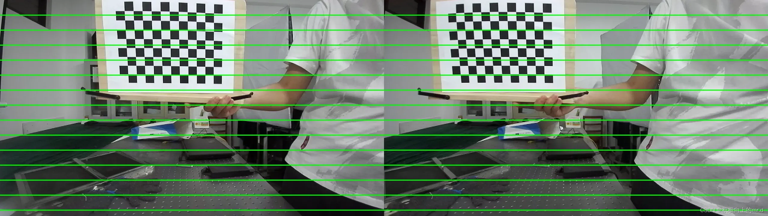
5、通过上述的两个整体旋转矩阵,就能够得到理想的平行配置的双目立体系图像。校正后根据需要对图像进行裁剪,需重新选择一个图像中心,和图像边缘从而让左、右叠加部分最大
校正后的效果图:
3.1.2 相关代码
def getRectifyTransform(height, width, config):
    # 读取内参和外参
    left_K = config.cam_matrix_left
    right_K = config.cam_matrix_right
    left_distortion = config.distortion_l
    right_distortion = config.distortion_r
    R = config.R
    T = config.T

    # 计算校正变换
    R1, R2, P1, P2, Q, roi1, roi2 = cv2.stereoRectify(left_K, left_distortion, right_K, right_distortion,
                                                      (width, height), R, T, alpha=0)
    map1x, map1y = cv2.initUndistortRectifyMap(left_K, left_distortion, R1, P1, (width, height), cv2.CV_32FC1)
    map2x, map2y = cv2.initUndistortRectifyMap(right_K, right_distortion, R2, P2, (width, height), cv2.CV_32FC1)

    return map1x, map1y, map2x, map2y, Q


# 畸变校正和立体校正
def rectifyImage(image1, image2, map1x, map1y, map2x, map2y):
    rectifyed_img1 = cv2.remap(image1, map1x, map1y, cv2.INTER_AREA)
    rectifyed_img2 = cv2.remap(image2, map2x, map2y, cv2.INTER_AREA)

    return rectifyed_img1, rectifyed_img2
注意:立体校正前应先进行消除畸变处理
3.2 立体匹配和视差计算
立体匹配也称作视差估计,立体匹配可划分为四个步骤:匹配代价计算、代价聚合、视差计算和视差优化。立体校正后的左右两幅图像得到后,匹配点是在同一行上的,可以使用OpenCV中的BM算法或者SGBM算法计算视差图。由于SGBM算法的表现要远远优于BM算法,因此采用SGBM算法获取视差图。在立体匹配生成视差图后,可以对视差图进行后处理,如滤波,空洞填充等方法,从而改善视差图的视觉效果
相关代码
def stereoMatchSGBM(left_image, right_image, down_scale=False):
    # SGBM匹配参数设置
    if left_image.ndim == 2:
        img_channels = 1
    else:
        img_channels = 3
    blockSize = 3
    paraml = {'minDisparity': 0,
              'numDisparities': 64,
              'blockSize': blockSize,
              'P1': 8 * img_channels * blockSize ** 2,
              'P2': 32 * img_channels * blockSize ** 2,
              'disp12MaxDiff': 1,
              'preFilterCap': 63,
              'uniquenessRatio': 15,
              'speckleWindowSize': 100,
              'speckleRange': 1,
              'mode': cv2.STEREO_SGBM_MODE_SGBM_3WAY
              }

    # 构建SGBM对象
    left_matcher = cv2.StereoSGBM_create(**paraml)
    paramr = paraml
    paramr['minDisparity'] = -paraml['numDisparities']
    right_matcher = cv2.StereoSGBM_create(**paramr)

    # 计算视差图
    size = (left_image.shape[1], left_image.shape[0])
    if down_scale == False:
        disparity_left = left_matcher.compute(left_image, right_image)
        disparity_right = right_matcher.compute(right_image, left_image)
    else:
        left_image_down = cv2.pyrDown(left_image)
        right_image_down = cv2.pyrDown(right_image)
        factor = left_image.shape[1] / left_image_down.shape[1]

        disparity_left_half = left_matcher.compute(left_image_down, right_image_down)
        disparity_right_half = right_matcher.compute(right_image_down, left_image_down)
        disparity_left = cv2.resize(disparity_left_half, size, interpolation=cv2.INTER_AREA)
        disparity_right = cv2.resize(disparity_right_half, size, interpolation=cv2.INTER_AREA)
        disparity_left = factor * disparity_left
        disparity_right = factor * disparity_right

    # 真实视差(因为SGBM算法得到的视差是×16的)
    trueDisp_left = disparity_left.astype(np.float32) / 16.
    trueDisp_right = disparity_right.astype(np.float32) / 16.

    return trueDisp_left, trueDisp_right
3.3 深度计算
得到视差图后,计算像素深度值,公式如下:
depth = ( f * baseline) / disp
其中,depth表示深度图;f表示归一化的焦距,也就是内参中的fx; baseline是两个相机光心之间的距离,称作基线距离;disp是视差值
实验直接利用opencv中的cv2.reprojectImageTo3D()函数计算深度图,代码如下
def getDepthMapWithQ(disparityMap: np.ndarray, Q: np.ndarray) -> np.ndarray:
    points_3d = cv2.reprojectImageTo3D(disparityMap, Q)
    depthMap = points_3d[:, :, 2]
    reset_index = np.where(np.logical_or(depthMap < 0.0, depthMap > 65535.0))
    depthMap[reset_index] = 0
    return depthMap.astype(np.float32)
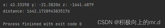
测距结果:
3.4 注意事项
双目测距效果跟很多因素相关,光线强弱、背景杂乱、目标物距离过远过近、标定误差大小都会影响,大家根据自己的情况寻找相关原因,最后希望大家都可以获得一个较好的测距效果
4. 完整代码
import sys
import cv2
import numpy as np
import stereoconfig

# 预处理
def preprocess(img1, img2):
    # 彩色图->灰度图
    if (img1.ndim == 3):      #判断是否为三维数组
        img1 = cv2.cvtColor(img1, cv2.COLOR_BGR2GRAY)  # 通过OpenCV加载的图像通道顺序是BGR
    if (img2.ndim == 3):
        img2 = cv2.cvtColor(img2, cv2.COLOR_BGR2GRAY)

    # 直方图均衡
    img1 = cv2.equalizeHist(img1)
    img2 = cv2.equalizeHist(img2)

    return img1, img2


# 消除畸变
def undistortion(image, camera_matrix, dist_coeff):
    undistortion_image = cv2.undistort(image, camera_matrix, dist_coeff)

    return undistortion_image

# 获取畸变校正和立体校正的映射变换矩阵、重投影矩阵
# @param:config是一个类,存储着双目标定的参数:config = stereoconfig.stereoCamera()
def getRectifyTransform(height, width, config):
    # 读取内参和外参
    left_K = config.cam_matrix_left
    right_K = config.cam_matrix_right
    left_distortion = config.distortion_l
    right_distortion = config.distortion_r
    R = config.R
    T = config.T

    # 计算校正变换
    R1, R2, P1, P2, Q, roi1, roi2 = cv2.stereoRectify(left_K, left_distortion, right_K, right_distortion,
                                                      (width, height), R, T, alpha=0)

    map1x, map1y = cv2.initUndistortRectifyMap(left_K, left_distortion, R1, P1, (width, height), cv2.CV_32FC1)
    map2x, map2y = cv2.initUndistortRectifyMap(right_K, right_distortion, R2, P2, (width, height), cv2.CV_32FC1)

    return map1x, map1y, map2x, map2y, Q


# 畸变校正和立体校正
def rectifyImage(image1, image2, map1x, map1y, map2x, map2y):
    rectifyed_img1 = cv2.remap(image1, map1x, map1y, cv2.INTER_AREA)
    rectifyed_img2 = cv2.remap(image2, map2x, map2y, cv2.INTER_AREA)

    return rectifyed_img1, rectifyed_img2


# 立体校正检验----画线
def draw_line(image1, image2):
    # 建立输出图像
    height = max(image1.shape[0], image2.shape[0])
    width = image1.shape[1] + image2.shape[1]

    output = np.zeros((height, width, 3), dtype=np.uint8)
    output[0:image1.shape[0], 0:image1.shape[1]] = image1
    output[0:image2.shape[0], image1.shape[1]:] = image2

    # 绘制等间距平行线
    line_interval = 50  # 直线间隔:50
    for k in range(height // line_interval):
        cv2.line(output, (0, line_interval * (k + 1)), (2 * width, line_interval * (k + 1)), (0, 255, 0), thickness=2,
                 lineType=cv2.LINE_AA)

    return output

# 视差计算
def stereoMatchSGBM(left_image, right_image, down_scale=False):
    # SGBM匹配参数设置
    if left_image.ndim == 2:
        img_channels = 1
    else:
        img_channels = 3
    blockSize = 3
    paraml = {'minDisparity': 0,
              'numDisparities': 64,
              'blockSize': blockSize,
              'P1': 8 * img_channels * blockSize ** 2,
              'P2': 32 * img_channels * blockSize ** 2,
              'disp12MaxDiff': 1,
              'preFilterCap': 63,
              'uniquenessRatio': 15,
              'speckleWindowSize': 100,
              'speckleRange': 1,
              'mode': cv2.STEREO_SGBM_MODE_SGBM_3WAY
              }

    # 构建SGBM对象
    left_matcher = cv2.StereoSGBM_create(**paraml)
    paramr = paraml
    paramr['minDisparity'] = -paraml['numDisparities']
    right_matcher = cv2.StereoSGBM_create(**paramr)

    # 计算视差图
    size = (left_image.shape[1], left_image.shape[0])
    if down_scale == False:
        disparity_left = left_matcher.compute(left_image, right_image)
        disparity_right = right_matcher.compute(right_image, left_image)
    else:
        left_image_down = cv2.pyrDown(left_image)
        right_image_down = cv2.pyrDown(right_image)
        factor = left_image.shape[1] / left_image_down.shape[1]

        disparity_left_half = left_matcher.compute(left_image_down, right_image_down)
        disparity_right_half = right_matcher.compute(right_image_down, left_image_down)
        disparity_left = cv2.resize(disparity_left_half, size, interpolation=cv2.INTER_AREA)
        disparity_right = cv2.resize(disparity_right_half, size, interpolation=cv2.INTER_AREA)
        disparity_left = factor * disparity_left
        disparity_right = factor * disparity_right

    # 真实视差(因为SGBM算法得到的视差是×16的)
    trueDisp_left = disparity_left.astype(np.float32) / 16.
    trueDisp_right = disparity_right.astype(np.float32) / 16.

    return trueDisp_left, trueDisp_right

def getDepthMapWithQ(disparityMap: np.ndarray, Q: np.ndarray) -> np.ndarray:
    points_3d = cv2.reprojectImageTo3D(disparityMap, Q)
    depthMap = points_3d[:, :, 2]
    reset_index = np.where(np.logical_or(depthMap < 0.0, depthMap > 65535.0))
    depthMap[reset_index] = 0

    return depthMap.astype(np.float32)

if __name__ == '__main__':
    # 读取图片
    iml = cv2.imread('L28.png', 1)  # 左图
    imr = cv2.imread('R28.png', 1)  # 右图
    if (iml is None) or (imr is None):
        print("Error: Images are empty, please check your image's path!")
        sys.exit(0)
    height, width = iml.shape[0:2]

    # 读取相机内参和外参
    # 使用之前先将标定得到的内外参数填写到stereoconfig.py中的StereoCamera类中
    config = stereoconfig.stereoCamera()
    print(config.cam_matrix_left)

    # 立体校正
    map1x, map1y, map2x, map2y, Q = getRectifyTransform(height, width, config)  # 获取用于畸变校正和立体校正的映射矩阵以及用于计算像素空间坐标的重投影矩阵
    iml_rectified, imr_rectified = rectifyImage(iml, imr, map1x, map1y, map2x, map2y)
    print(Q)

    # 绘制等间距平行线,检查立体校正的效果
    line = draw_line(iml_rectified, imr_rectified)
    cv2.imwrite('check_rectification.png', line)

    # 立体匹配
    iml_, imr_ = preprocess(iml, imr)  # 预处理,一般可以削弱光照不均的影响,不做也可以
    disp, _ = stereoMatchSGBM(iml, imr, False)  # 这里传入的是未经立体校正的图像,因为我们使用的middleburry图片已经是校正过的了
    cv2.imwrite('disaprity.png', disp * 4)

    fx = config.cam_matrix_left[0, 0]
    fy = fx
    cx = config.cam_matrix_left[0, 2]
    cy = config.cam_matrix_left[1, 2]
    print(fx, fy, cx, cy)

    # 计算像素点的3D坐标(左相机坐标系下)
    points_3d = cv2.reprojectImageTo3D(disp, Q)  # 参数中的Q就是由getRectifyTransform()函数得到的重投影矩阵
    # 设置想要检测的像素点坐标(x,y)
    x=640
    y=360
    print('x:',points_3d[int(y), int(x), 0],'y:',points_3d[int(y), int(x), 1],'z:',points_3d[int(y), int(x), 2])      # 得出像素点的三维坐标,单位mm
    print('distance:',(points_3d[int(y), int(x), 0] ** 2 + points_3d[int(y), int(x), 1] ** 2 + points_3d[int(y), int(x), 2] ** 2) ** 0.5)      # 计算距离,单位mm
大致就写到这里,有问题可以在评论区讨论
文章出处登录后可见!