本文是你真的理解高性能吗-预处理高性能_哔哩哔哩_bilibiq的学习笔记!
预处理指的是 把图像变成 tensor 输入到神经网络去的过程。
首先看 YOLOX 的实现:YOLOX/yolox.cpp at main · Megvii-BaseDetection/YOLOX · GitHub
    cv::Mat img = cv::imread(input_image_path);
    int img_w = img.cols;
    int img_h = img.rows;
    cv::Mat pr_img = static_resize(img);
    std::cout << "blob image" << std::endl;

    float* blob;
    blob = blobFromImage(pr_img); // blob 就是输入到神经网络的tensor
cv::Mat static_resize(cv::Mat& img) {
float r = std::min(INPUT_W / (img.cols*1.0), INPUT_H / (img.rows*1.0));
// r = std::min(r, 1.0f);
int unpad_w = r * img.cols;
int unpad_h = r * img.rows;
cv::Mat re(unpad_h, unpad_w, CV_8UC3);
cv::resize(img, re, re.size());
cv::Mat out(INPUT_H, INPUT_W, CV_8UC3, cv::Scalar(114, 114, 114));
re.copyTo(out(cv::Rect(0, 0, re.cols, re.rows)));
return out;
}缺点:低效,Mat 分配了两次,是CPU实现,效率低。
float* blobFromImage(cv::Mat& img){
    float* blob = new float[img.total()*3];
    int channels = 3;
    int img_h = img.rows;
    int img_w = img.cols;
    for (size_t c = 0; c < channels; c++)
    {
        for (size_t  h = 0; h < img_h; h++)
        {
            for (size_t w = 0; w < img_w; w++)
            {
                blob[c * img_w * img_h + h * img_w + w] =
                    (float)img.at<cv::Vec3b>(h, w)[c];
            }
        }
    }
    return blob;
}
缺点:性能差,3个for循环,CPU实现,效率低。
再看下 YOLOv5实现:https://github.com/wang-xinyu/tensorrtx/commit/e7a5f0acbc5f8879d90f6d387f5fb3e4ec52a1e5
该代码库在 2021年10月19日更新后也是使用了仿射变换在GPU上进行预处理。但我们先看之前的版本。
        for (int b = 0; b < fcount; b++) {
            cv::Mat img = cv::imread(img_dir + "/" + file_names[f - fcount + 1 + b]);
            if (img.empty()) continue;
            cv::Mat pr_img = preprocess_img(img, INPUT_W, INPUT_H); // letterbox BGR to RGB
            int i = 0;
            for (int row = 0; row < INPUT_H; ++row) {
                uchar* uc_pixel = pr_img.data + row * pr_img.step;
                for (int col = 0; col < INPUT_W; ++col) {
                    data[b * 3 * INPUT_H * INPUT_W + i] = (float)uc_pixel[2] / 255.0;
                    data[b * 3 * INPUT_H * INPUT_W + i + INPUT_H * INPUT_W] = (float)uc_pixel[1] / 255.0;
                    data[b * 3 * INPUT_H * INPUT_W + i + 2 * INPUT_H * INPUT_W] = (float)uc_pixel[0] / 255.0;
                    uc_pixel += 3;
                    ++i;
                }
            }
        // Run inference
        auto start = std::chrono::system_clock::now(); // 这里的推理时间都没有考虑预处理,因此是假的推理时间。
两个for循环,效率低。
preprocess_img函数在tensorrtx/utils.h at master · wang-xinyu/tensorrtx · GitHub
static inline cv::Mat preprocess_img(cv::Mat& img, int input_w, int input_h) {
    int w, h, x, y;
    float r_w = input_w / (img.cols*1.0);
    float r_h = input_h / (img.rows*1.0);
    if (r_h > r_w) {
        w = input_w;
        h = r_w * img.rows;
        x = 0;
        y = (input_h - h) / 2;
    } else {
        w = r_h * img.cols;
        h = input_h;
        x = (input_w - w) / 2;
        y = 0;
    }
    cv::Mat re(h, w, CV_8UC3);
    cv::resize(img, re, re.size(), 0, 0, cv::INTER_LINEAR);
    cv::Mat out(input_h, input_w, CV_8UC3, cv::Scalar(128, 128, 128));
    re.copyTo(out(cv::Rect(x, y, re.cols, re.rows)));
    return out;
}
计算上比YOLOX的还复杂,有if 代码可读性差,YOLOX很可能抄袭的该代码。
后期处理:
            cv::Mat img = cv::imread(img_dir + "/" + file_names[f - fcount + 1 + b]);
            for (size_t j = 0; j < res.size(); j++) {
                cv::Rect r = get_rect(img, res[j].bbox);  // 框恢复成图像大小,然后显示出来。
@@ -420,17 +419,22 @@ int main(int argc, char** argv) {
            cv::imwrite("_" + file_names[f - fcount + 1 + b], img);
        }
https://github.com/wang-xinyu/tensorrtx/blob/master/yolov5/common.hpp:get_rect
cv::Rect get_rect(cv::Mat& img, float bbox[4]) {
    float l, r, t, b;
    float r_w = Yolo::INPUT_W / (img.cols * 1.0);
    float r_h = Yolo::INPUT_H / (img.rows * 1.0);
    if (r_h > r_w) {
        l = bbox[0] - bbox[2] / 2.f;
        r = bbox[0] + bbox[2] / 2.f;
        t = bbox[1] - bbox[3] / 2.f - (Yolo::INPUT_H - r_w * img.rows) / 2;
        b = bbox[1] + bbox[3] / 2.f - (Yolo::INPUT_H - r_w * img.rows) / 2;
        l = l / r_w;
        r = r / r_w;
        t = t / r_w;
        b = b / r_w;
    } else {
        l = bbox[0] - bbox[2] / 2.f - (Yolo::INPUT_W - r_h * img.cols) / 2;
        r = bbox[0] + bbox[2] / 2.f - (Yolo::INPUT_W - r_h * img.cols) / 2;
        t = bbox[1] - bbox[3] / 2.f;
        b = bbox[1] + bbox[3] / 2.f;
        l = l / r_h;
        r = r / r_h;
        t = t / r_h;
        b = b / r_h;
    }
    return cv::Rect(round(l), round(t), round(r - l), round(b - t));
}
代码可读性差,难以编写!
性能有多高?
使用warpaffine(仿射变换)实现预处理。
图像预处理的本质是将图像缩小,然后将其移动到特定位置。目标检测器通常按比例缩放+居中以实现预处理。
可以使用 warpaffine 来做。
问题:是否比 resize 慢呢? 并不是,warpaffine需要做插值,resize也要做插值,本质上一样的。
使用warpaffine 用矩阵来描述更加方便,操作简单,预处理和后处理会更加简洁。
两行代码预处理,后处理恢复原图大小,逆矩阵相乘。简洁的! ! !
- warpaffine 并不会加速,只是逻辑上更清晰。加速的话需要在GPU上实现仿射变换的过程。
关于转换
- 点的变换,通常存在,缩放、旋转、平移,例如对点P(x, y)进行旋转𝜃度、缩放scale倍、平移ox,oy
旋转变换:
- 如果用矩阵表示,则有:

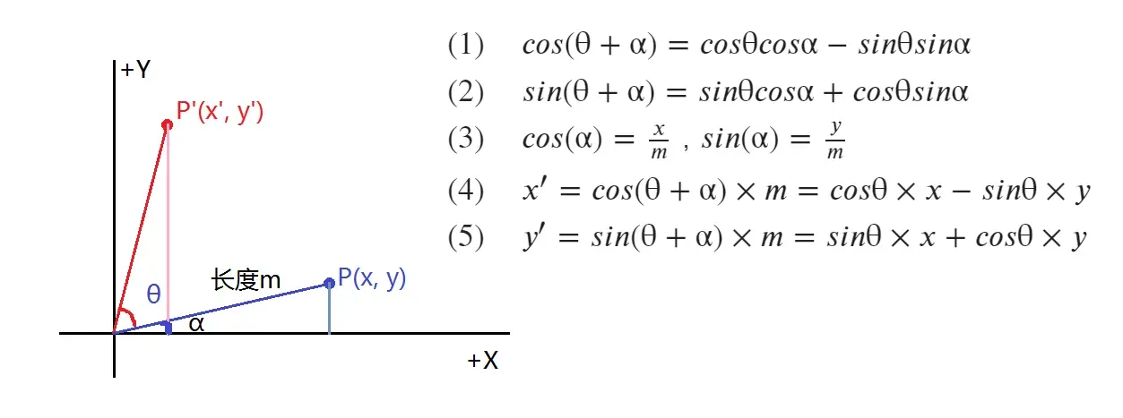
- 又因为opencv的图像坐标,原点在左上角,y+向下,因此旋转变换矩阵在图像上时是:

注意:这里是逆时针旋转,如果是顺时针或者:

参考:仿射变换(Affine Transformation)原理及应用(1)_Godswisdom的博客-CSDN博客_affine transformation
import cv2
import numpy as np
cv2.getRotationMatrix2D((0, 0), 60, 1), np.sin(60/180.0*np.pi)
输出:这里忽略第三列。
(array([[ 0.5      ,  0.8660254,  0.       ],
        [-0.8660254,  0.5      ,  0.       ]]),
 0.8660254037844386)
缩放变换

注意:公式中x,y 缩放是一样的,这里可以不同。
缩放 + 旋转变换 = 旋转 + 缩放变换

核实:
theta = 0.8
scale = 2
rot = np.array([
    [np.cos(theta), np.sin(theta)],
    [-np.sin(theta), np.cos(theta)]
])

sca = np.array([
    [scale, 0],
    [0, scale]
])

np.allclose(rot @ sca, sca @ rot)

# True
翻译转换

- 这时候问题就来了。平移是加法运算,没有办法将其组合成矩阵。我该怎么办?
解决:
齐次坐标定义
用(x, y, w),来表示点
翻译转换
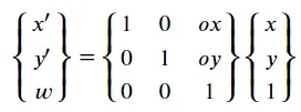
缩放+旋转+平移变换
(注意此时顺序有关,旋转缩放后,再平移的样子,也就是P’ = T x S x R x P)
R:旋转;S:缩放;T:平移;P原来点;得到的结果

旋转矩阵的逆是它的转置,即
![]()
逆变换,反转变换矩阵
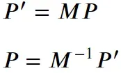
对于正常的目标检测推断,通常需要按比例缩放和居中图像


它分为以下三个步骤:
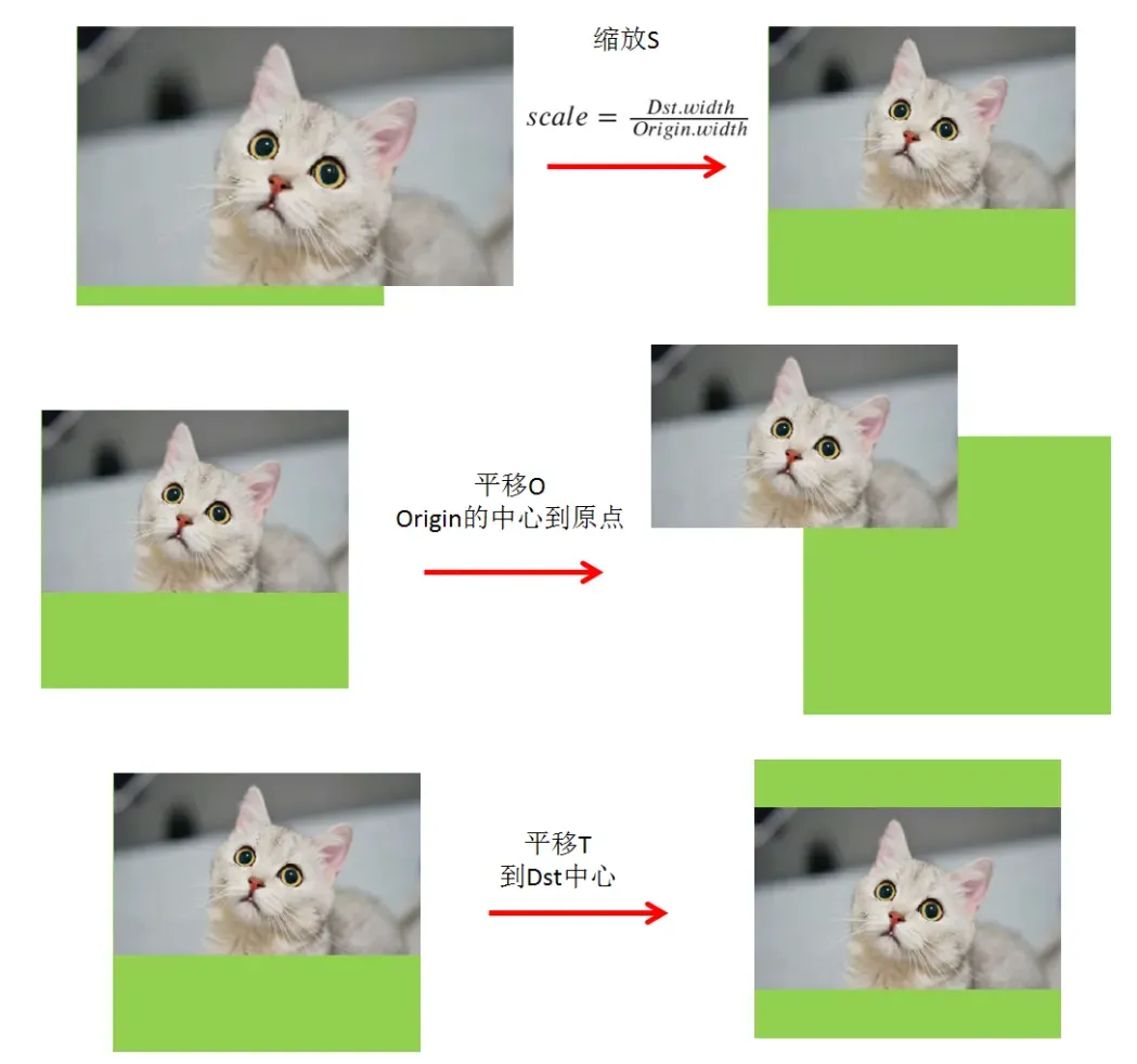


由于变换比较简单,所以逆变换可以很容易地写成:
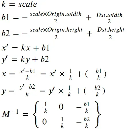
作者实现的仿射变换:
        float i2d[6];       // image to dst(network), 2x3 matrix
        float d2i[6];       // dst to image, 2x3 matrix

        void compute(const cv::Size& from, const cv::Size& to){
            float scale_x = to.width / (float)from.width;
            float scale_y = to.height / (float)from.height;

            // 这里取min的理由是
            // 1. M矩阵是 from * M = to的方式进行映射,因此scale的分母一定是from
            // 2. 取最小,即根据宽高比,算出最小的比例,如果取最大,则势必有一部分超出图像范围而被裁剪掉,这不是我们要的
            // **
            float scale = std::min(scale_x, scale_y);

            /**
            这里的仿射变换矩阵实质上是2x3的矩阵,具体实现是
            scale, 0, -scale * from.width * 0.5 + to.width * 0.5
            0, scale, -scale * from.height * 0.5 + to.height * 0.5

            这里可以想象成,是经历过缩放、平移、平移三次变换后的组合,M = TPS
            例如第一个S矩阵,定义为把输入的from图像,等比缩放scale倍,到to尺度下
            S = [
            scale,     0,      0
            0,     scale,      0
            0,         0,      1
            ]

            P矩阵定义为第一次平移变换矩阵,将图像的原点,从左上角,移动到缩放(scale)后图像的中心上
            P = [
            1,        0,      -scale * from.width * 0.5
            0,        1,      -scale * from.height * 0.5
            0,        0,                1
            ]

            T矩阵定义为第二次平移变换矩阵,将图像从原点移动到目标(to)图的中心上
            T = [
            1,        0,      to.width * 0.5,
            0,        1,      to.height * 0.5,
            0,        0,            1
            ]

            通过将3个矩阵顺序乘起来,即可得到下面的表达式:
            M = [
            scale,    0,     -scale * from.width * 0.5 + to.width * 0.5
            0,     scale,    -scale * from.height * 0.5 + to.height * 0.5
            0,        0,                     1
            ]
            去掉第三行就得到opencv需要的输入2x3矩阵
            **/

            /*
                 + scale * 0.5 - 0.5 的主要原因是使得中心更加对齐,下采样不明显,但是上采样时就比较明显
                参考:https://www.iteye.com/blog/handspeaker-1545126
            */
            i2d[0] = scale;  i2d[1] = 0;  i2d[2] = -scale * from.width  * 0.5  + to.width * 0.5 + scale * 0.5 - 0.5;
            i2d[3] = 0;  i2d[4] = scale;  i2d[5] = -scale * from.height * 0.5 + to.height * 0.5 + scale * 0.5 - 0.5;

            cv::Mat m2x3_i2d(2, 3, CV_32F, i2d);
            cv::Mat m2x3_d2i(2, 3, CV_32F, d2i);
            cv::invertAffineTransform(m2x3_i2d, m2x3_d2i);  // 求逆矩阵
        }

        cv::Mat i2d_mat(){
            return cv::Mat(2, 3, CV_32F, i2d);
        }
    };
核实
origin = np.array([300, 500], dtype=float)
dst = np.array([640, 640], dtype=float)
scale = min(dst/origin)

M = np.array([
    [scale, 0, -(scale * origin[0] * 0.5) + (dst[0] * 0.5)],
    [0, scale, -(scale * origin[1] * 0.5) + (dst[1] * 0.5)],
    [0, 0, 1]
])

# array([[  1.28,   0.  , 128.  ],
#        [  0.  ,   1.28,   0.  ],
#        [  0.  ,   0.  ,   1.  ]])
np.linalg.inv(M)
# array([[ 0.78125, 0. , -100. ],
# [ 0. , 0.78125, 0. ],
# [ 0. , 0. , 1. ]])k = scale
b1 = M[0, 2]
b2 = M[1, 2]
invM = np.array([
[1 / k, 0, -b1/k],
[0, 1 / k, -b2/k]
])
invM
# array([[ 0.78125, 0. , -100. ],
# [ 0. , 0.78125, -0. ]])做一个正变换和逆变换的实验看看
def inv_align(M):
    k = M[0, 0]
    b1 = M[0, 2]
    b2 = M[1, 2]
    return np.array([
        [1/k, 0, -b1/k],
        [0, 1/k, -b2/k]
    ])

def align(image, dst_size):

    oh, ow = image.shape[:2]
    dh, dw = dst_size
    scale = min(dw/ow, dh/oh)

    M = np.array([
        [scale, 0, -scale * ow * 0.5 + dw * 0.5],
        [0, scale, -scale * oh * 0.5 + dh * 0.5]
    ])
    return cv2.warpAffine(image, M, dst_size), M, inv_align(M)
import matplotlib.pyplot as plt
cat1 = cv2.imread("cat1.png")
acat1, M, inv = align(cat1, (640, 640))
plt.subplot(1, 2, 1)
plt.title("WarpAffine")
plt.imshow(acat1[..., ::-1])
resact1 = cv2.warpAffine(acat1, inv, cat1.shape[:2][::-1])
plt.subplot(1, 2, 2)
plt.title("Restore")
plt.imshow(resact1[..., ::-1])
import matplotlib.pyplot as plt

cat2 = cv2.imread("cat2.png")
acat2, M, inv = align(cat2, (640, 640))

plt.subplot(1, 2, 1)
plt.title("WarpAffine")
plt.imshow(acat2[..., ::-1])

resact2 = cv2.warpAffine(acat2, inv, cat2.shape[:2][::-1])
plt.subplot(1, 2, 2)
plt.title("Restore")
plt.imshow(resact2[..., ::-1])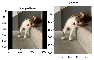
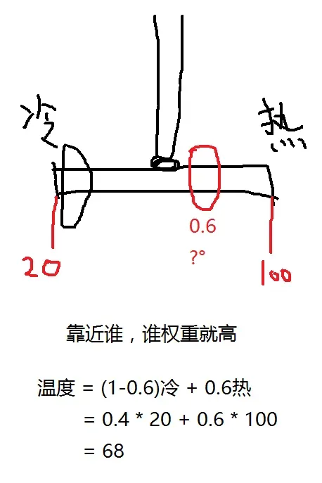
线性插值
p0 = 20    # 冷水
p1 = 100   # 热水
pos = 0.6  # 应该多少度

value = (1 - pos) * p0 + pos * p1
value
# 68.0
双线性插值
# 0, 0
p0 = 3;        p1 = 5
p2 = 6;        p3 = 8
#                    1, 1

# x , y
pos = 0.6, 0.8

p0_area = (1 - pos[0]) * (1 - pos[1])
p1_area = pos[0] * (1 - pos[1])
p2_area = (1 - pos[0]) * pos[1]
p3_area = pos[0] * pos[1]

value = p0_area * p0 + p1_area * p1 + p2_area * p2 + p3_area * p3
value
# 6.6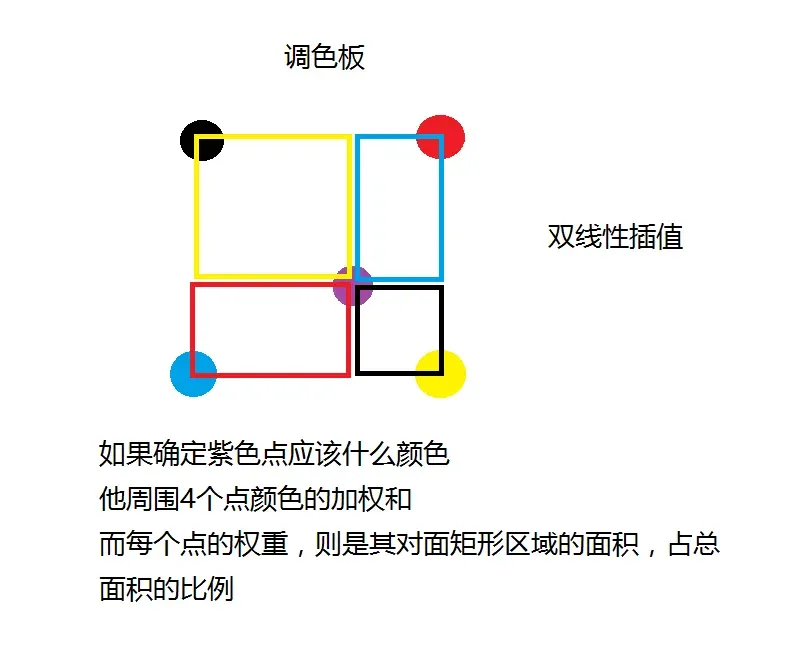
实现一个warpaffine,双线性插值
def pyWarpAffine(image, M, dst_size, constant=(0, 0, 0)):

    # 注意输入的M矩阵格式,是Origin->Dst
    # 而这里需要的是Dst->Origin,所以要取逆矩阵
    M = cv2.invertAffineTransform(M)
    constant = np.array(constant)
    ih, iw   = image.shape[:2]
    dw, dh   = dst_size
    dst      = np.full((dh, dw, 3), constant, dtype=np.uint8)
    irange   = lambda p: p[0] >= 0 and p[0] < iw and p[1] >= 0 and p[1] < ih

    for y in range(dh): # 循环的是输出图的大小,原图大还是一样的快;循环容易cuda核并行
        for x in range(dw):

            homogeneous = np.array([[x, y, 1]]).T
            ox, oy = M @ homogeneous

            low_ox = int(np.floor(ox))
            low_oy = int(np.floor(oy))
            high_ox = low_ox + 1
            high_oy = low_oy + 1

            # p0     p1
            #      o
            # p2     p3

            pos = ox - low_ox, oy - low_oy
            p0_area = (1 - pos[0]) * (1 - pos[1])
            p1_area = pos[0] * (1 - pos[1])
            p2_area = (1 - pos[0]) * pos[1]
            p3_area = pos[0] * pos[1]

            p0 = low_ox, low_oy
            p1 = high_ox, low_oy
            p2 = low_ox, high_oy
            p3 = high_ox, high_oy
            p0_value = image[p0[1], p0[0]] if irange(p0) else constant
            p1_value = image[p1[1], p1[0]] if irange(p1) else constant
            p2_value = image[p2[1], p2[0]] if irange(p2) else constant
            p3_value = image[p3[1], p3[0]] if irange(p3) else constant
            dst[y, x] = p0_area * p0_value + p1_area * p1_value + p2_area * p2_value + p3_area * p3_value
            # 解锁:resize    透视变换   设计双线性插值的地方
            # 学习warpAffine,熟练掌握它,然后使用cuda核实现它,前处理速度大幅提升。
            # 交换bgr  rgb
            # normalize ->  -mean /std
            # 1行代码实现normalize , /255.0
            # bgr bgr bgr -> bbb ggg rrr
            # focus 本质是切片
            # focus offset, 1行代码实现focus 性能高

    return dst


cat1 = cv2.imread("cat1.png")
#acat1_cv, M, inv = align(cat1, (100, 100))
M = cv2.getRotationMatrix2D((0, 0), 30, 0.5)
acat1_cv = cv2.warpAffine(cat1, M, (100, 100))
acat1_py = pyWarpAffine(cat1, M, (100, 100))

plt.figure(figsize=(10, 10))
plt.subplot(1, 2, 1)
plt.title("OpenCV")
plt.imshow(acat1_cv[..., ::-1])

plt.subplot(1, 2, 2)
plt.title("PyWarpAffine")
plt.imshow(acat1_py[..., ::-1])
下一步是什么
学习和研究:https://github.com/Guanbin-Huang/tensorRT_Pro_co-comments/blob/main/src/tensorRT/common/preprocess_kernel.cu
文章出处登录后可见!

