本篇文章旨在记录我电赛期间使用openmv和stm32单片机之间进行串口通信,将openmv识别到的坐标传输给单片机。背景是基于2023年全国大学生电子设计大赛E题:舵机云台追踪识别。
单片机的串口通信原理我便不再详细讲解,下面直接上代码分析。
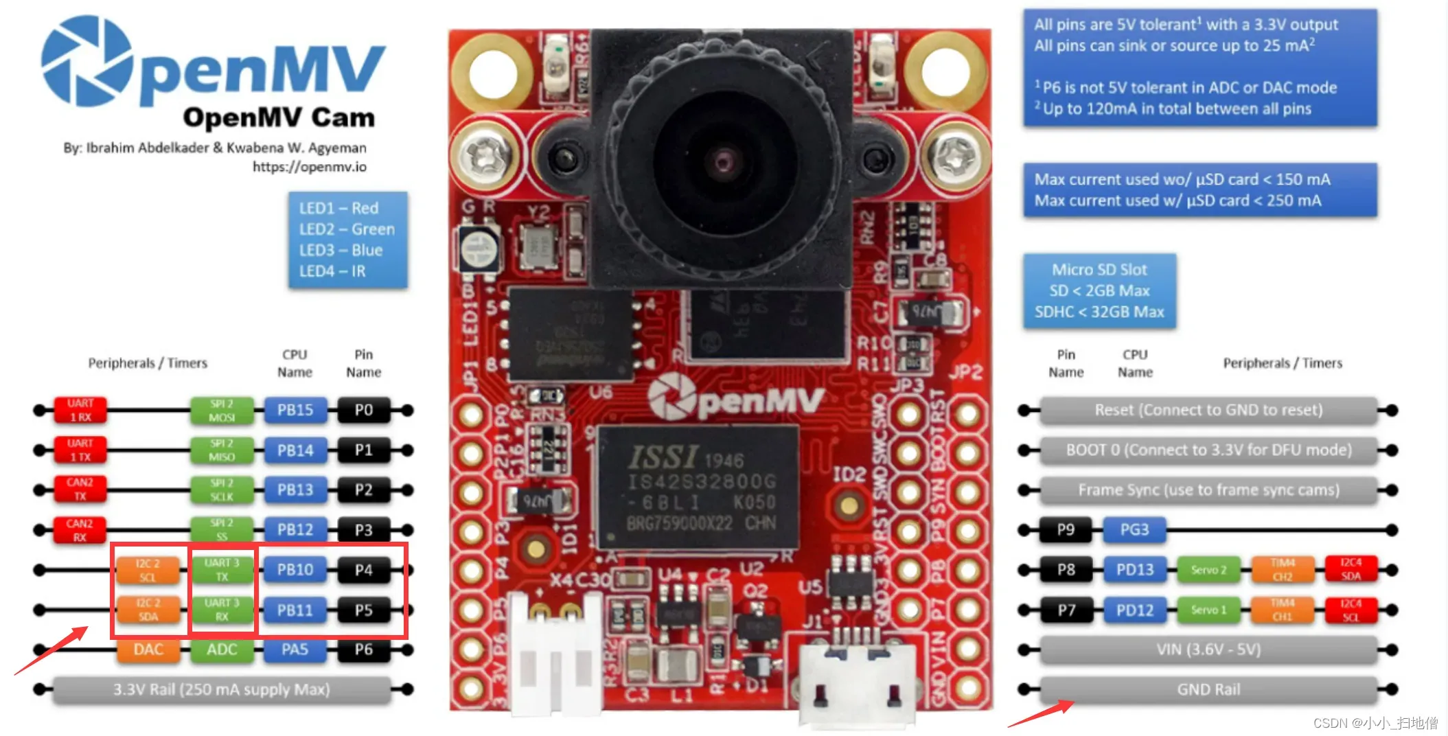
值得注意的是接线:RX——>TX
TX——>RX
单片机和OPENMV必须共地
非常重要!!!!
一、串口通信传输两个数据(x坐标和y坐标)
(一)、 OPENMV串口通信部分
import sensor, image, time,math,pyb
from pyb import UART,LED
import json
import ustruct

sensor.reset()
sensor.set_pixformat(sensor.RGB565)
sensor.set_framesize(sensor.QVGA)
sensor.skip_frames(time = 2000)
sensor.set_auto_gain(False) # must be turned off for color tracking
sensor.set_auto_whitebal(False) # must be turned off for color tracking
red_threshold_01=(10, 100, 127, 32, -43, 67)
clock = time.clock()

uart = UART(3,115200)   #定义串口3变量
uart.init(115200, bits=8, parity=None, stop=1) # init with given parameters

def find_max(blobs):    #定义寻找色块面积最大的函数
    max_size=0
    for blob in blobs:
        if blob.pixels() > max_size:
            max_blob=blob
            max_size = blob.pixels()
    return max_blob


def sending_data(cx,cy,cw,ch):
    global uart;
    #frame=[0x2C,18,cx%0xff,int(cx/0xff),cy%0xff,int(cy/0xff),0x5B];
    #data = bytearray(frame)
    data = ustruct.pack("<bbhhhhb",      #格式为俩个字符俩个短整型(2字节)
                   0x2C,                      #帧头1
                   0x12,                      #帧头2
                   int(cx), # up sample by 4   #数据1
                   int(cy), # up sample by 4    #数据2
                   int(cw), # up sample by 4    #数据1
                   int(ch), # up sample by 4    #数据2
                   0x5B)
    uart.write(data);   #必须要传入一个字节数组


while(True):
    clock.tick()
    img = sensor.snapshot()
    blobs = img.find_blobs([red_threshold_01])
    max_b = find_max(blobs)
    cx=0;cy=0;
    if blobs:
            #如果找到了目标颜色
            cx=max_b[5]
            cy=max_b[6]
            cw=max_b[2]
            ch=max_b[3]
            img.draw_rectangle(max_b[0:4]) # rect
            img.draw_cross(max_b[5], max_b[6]) # cx, cy
            FH = bytearray([0x2C,0x12,cx,cy,cw,ch,0x5B])
            #sending_data(cx,cy,cw,ch)
            uart.write(FH)
            print(cx,cy,cw,ch)
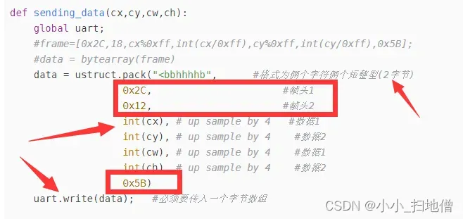
注意观察下图标注的部分,我不做详细讲解,但是很容易理解:
接下来请看STM32串口通信部分的代码:
#include "uart.h"
#include "oled.h"
#include "stdio.h"

static u8 Cx=0,Cy=0,Cw=0,Ch=0;

void USART1_Init(void)
{
	//USART1_TX:PA 9
	//USART1_RX:PA10
	GPIO_InitTypeDef GPIO_InitStructure;     //串口端口配置结构体变量
	USART_InitTypeDef USART_InitStructure;   //串口参数配置结构体变量
	NVIC_InitTypeDef NVIC_InitStructure;     //串口中断配置结构体变量

	RCC_APB2PeriphClockCmd(RCC_APB2Periph_USART1, ENABLE);
	RCC_APB2PeriphClockCmd(RCC_APB2Periph_GPIOA, ENABLE);   //打开PA端口时钟

    //USART1_TX   PA9
    GPIO_InitStructure.GPIO_Pin = GPIO_Pin_9;          		 //PA9
    GPIO_InitStructure.GPIO_Speed = GPIO_Speed_50MHz;  		 //设定IO口的输出速度为50MHz
    GPIO_InitStructure.GPIO_Mode = GPIO_Mode_AF_PP;	   		 //复用推挽输出
    GPIO_Init(GPIOA, &GPIO_InitStructure);             	 	 //初始化PA9
    //USART1_RX	  PA10
    GPIO_InitStructure.GPIO_Pin = GPIO_Pin_10;             //PA10
    GPIO_InitStructure.GPIO_Mode = GPIO_Mode_IN_FLOATING;  //浮空输入
    GPIO_Init(GPIOA, &GPIO_InitStructure);                 //初始化PA10

    //USART1 NVIC 配置
    NVIC_InitStructure.NVIC_IRQChannel = USART1_IRQn;
		NVIC_InitStructure.NVIC_IRQChannelPreemptionPriority=0 ;  //抢占优先级0
		NVIC_InitStructure.NVIC_IRQChannelSubPriority = 2;		  //子优先级2
		NVIC_InitStructure.NVIC_IRQChannelCmd = ENABLE;			  //IRQ通道使能
		NVIC_Init(&NVIC_InitStructure);	                          //根据指定的参数初始化VIC寄存器

    //USART 初始化设置
		USART_InitStructure.USART_BaudRate = 115200;                  //串口波特率为115200
		USART_InitStructure.USART_WordLength = USART_WordLength_8b;   //字长为8位数据格式
		USART_InitStructure.USART_StopBits = USART_StopBits_1;        //一个停止位
		USART_InitStructure.USART_Parity = USART_Parity_No;           //无奇偶校验位
		USART_InitStructure.USART_HardwareFlowControl = USART_HardwareFlowControl_None;   //无硬件数据流控制
		USART_InitStructure.USART_Mode = USART_Mode_Rx | USART_Mode_Tx;	                  //收发模式
    USART_Init(USART1, &USART_InitStructure);                     //初始化串口1

    USART_ITConfig(USART1, USART_IT_RXNE, ENABLE); //使能中断
    USART_Cmd(USART1, ENABLE);                     //使能串口1

  	//如下语句解决第1个字节无法正确发送出去的问题
	  USART_ClearFlag(USART1, USART_FLAG_TC);        //清串口1发送标志

}

//USART1 全局中断服务函数
void USART1_IRQHandler(void)
{
		u8 com_data;
		u8 i;
		static u8 RxCounter1=0;
		static u16 RxBuffer1[10]={0};
		static u8 RxState = 0;
		static u8 RxFlag1 = 0;


		if( USART_GetITStatus(USART1,USART_IT_RXNE)!=RESET)  	   //接收中断
		{
				USART_ClearITPendingBit(USART1,USART_IT_RXNE);   //清除中断标志
				com_data = USART_ReceiveData(USART1);

				if(RxState==0&&com_data==0x2C)  //0x2c帧头
				{
					RxState=1;
					RxBuffer1[RxCounter1++]=com_data;OLED_Refresh();
				}

				else if(RxState==1&&com_data==0x12)  //0x12帧头
				{
					RxState=2;
					RxBuffer1[RxCounter1++]=com_data;
				}

				else if(RxState==2)
				{
					RxBuffer1[RxCounter1++]=com_data;

					if(RxCounter1>=10||com_data == 0x5B)       //RxBuffer1接受满了,接收数据结束
					{
						RxState=3;
						RxFlag1=1;
						Cx=RxBuffer1[RxCounter1-5];
						Cy=RxBuffer1[RxCounter1-4];
						Cw=RxBuffer1[RxCounter1-3];
						Ch=RxBuffer1[RxCounter1-2];
					}
				}

				else if(RxState==3)		//检测是否接受到结束标志
				{
						if(RxBuffer1[RxCounter1-1] == 0x5B)
						{
									USART_ITConfig(USART1,USART_IT_RXNE,DISABLE);//关闭DTSABLE中断
									if(RxFlag1)
									{
									OLED_Refresh();
									OLED_ShowNum(0, 0,Cx,3,16,1);
									OLED_ShowNum(0,17,Cy,3,16,1);
									OLED_ShowNum(0,33,Cw,3,16,1);
									OLED_ShowNum(0,49,Ch,3,16,1);
									}
									RxFlag1 = 0;
									RxCounter1 = 0;
									RxState = 0;
									USART_ITConfig(USART1,USART_IT_RXNE,ENABLE);
						}
						else   //接收错误
						{
									RxState = 0;
									RxCounter1=0;
									for(i=0;i<10;i++)
									{
											RxBuffer1[i]=0x00;      //将存放数据数组清零
									}
						}
				}

				else   //接收异常
				{
						RxState = 0;
						RxCounter1=0;
						for(i=0;i<10;i++)
						{
								RxBuffer1[i]=0x00;      //将存放数据数组清零
						}
				}

		}

}
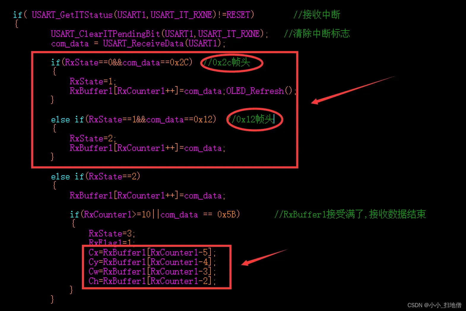
注意观察下面的图:
二、串口通信传输多个数据(四个点的x、y坐标同时传输给STM32单片机)
(一)OPENMV串口部分
from machine import Pin
import sensor, image, time, pyb
#import seekfree
from pyb import UART

# 初始化TFT180屏幕
#lcd = seekfree.LCD180(3)

# 初始化摄像头
sensor.reset()
sensor.set_pixformat(sensor.RGB565) # 设置图像色彩格式为RGB565格式
sensor.set_framesize(sensor.QQVGA)  # 设置图像大小为160*120
sensor.set_auto_whitebal(True)      # 设置自动白平衡
sensor.set_brightness(3000)         # 设置亮度为3000
sensor.skip_frames(time = 20)       # 跳过帧
uart = UART(3, 115200,timeout_char=3000) #配置串口
clock = time.clock()

def sending_data(cx,cy,cw,ch):
    global uart;
    data = ustruct.pack("<bbhhb",      #格式为俩个字符俩个短整型(2字节)
                   0x2C,                      #帧头1
                   0x12,                      #帧头2
                   int (cx1), # up sample by 4    #数据26
                   int (cy1),
                   int (cx2), # up sample by 4    #数据26
                   int (cy2),
                   int (cx3), # up sample by 4    #数据26
                   int (cy3),
                   int (cx4), # up sample by 4    #数据26
                   int (cy4),
                   0x5B)
    uart.write(data);   #必须要传入一个字节数组

while(True):
    clock.tick()
    img = sensor.snapshot()

# -----矩形框部分-----
    # 在图像中寻找矩形
    for r in img.find_rects(threshold = 10000):
        # 判断矩形边长是否符合要求
        if r.w() > 20 and r.h() > 20:
            # 在屏幕上框出矩形
            img.draw_rectangle(r.rect(), color = (255, 0, 0), scale = 4)
            # 获取矩形角点位置
            corner = r.corners()
            # 在屏幕上圈出矩形角点
            img.draw_circle(corner[0][0], corner[0][1], 5, color = (0, 0, 255), thickness = 2, fill = False)
            img.draw_circle(corner[1][0], corner[1][1], 5, color = (0, 0, 255), thickness = 2, fill = False)
            img.draw_circle(corner[2][0], corner[2][1], 5, color = (0, 0, 255), thickness = 2, fill = False)
            img.draw_circle(corner[3][0], corner[3][1], 5, color = (0, 0, 255), thickness = 2, fill = False)

        # 打印四个角点坐标, 角点1的数组是corner[0], 坐标就是(corner[0][0],corner[0][1])
        # 角点检测输出的角点排序每次不一定一致,矩形左上的角点有可能是corner0,1,2,3其中一个
            corner1_str = f"corner1 = ({corner[0][0]},{corner[0][1]})"
            corner2_str = f"corner2 = ({corner[1][0]},{corner[1][1]})"
            corner3_str = f"corner3 = ({corner[2][0]},{corner[2][1]})"
            corner4_str = f"corner4 = ({corner[3][0]},{corner[3][1]})"
        print(corner1_str + "\n" + corner2_str + "\n" + corner3_str + "\n" + corner4_str)
    # 显示到屏幕上,此部分会降低帧率
    #lcd.show_image(img, 160, 120, 0, 0, zoom=0)  #屏幕显示

    #串口通信传输的数据
        cx1=(int)(corner[0][0]*10)
        cy1=(int)(corner[0][1]*10)

        cx2=(int)(corner[1][0]*10)
        cy2=(int)(corner[1][1]*10)

        cx3=(int)(corner[2][0]*10)
        cy3=(int)(corner[2][1]*10)

        cx4=(int)(corner[3][0]*10)
        cy4=(int)(corner[3][1]*10)

        FH=bytearray([0x2C,0x12,cx1,cy1,cx2,cy2,cx3,cy3,cx4,cy4,0x5B])

        uart.write(FH)

        cx1=0
        cy1=0

        cx2=0
        cy2=0

        cx3=0
        cy3=0

        cx4=0
        cy4=0

    # 打印帧率
    print(clock.fps())
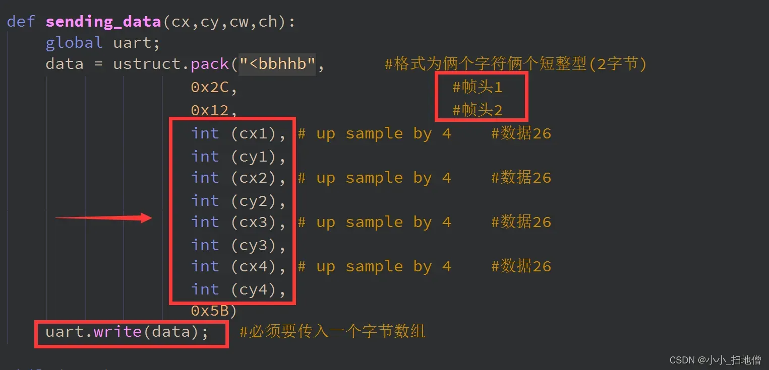
下面请观察这幅代码截图:
(二)、STM32串口通信部分
#include "stm32f10x.h" // Device header
#include <stdio.h>
#include <stdarg.h>
#include "OLED.h"
#include "LED.h"
#include "Serial.h"
uint8_t Serial_RxData;
uint8_t Serial_RxFlag;
static int16_t Cx1=0,Cy1=0,Cx2=0,Cy2=0,Cx3=0,Cy3=0,Cx4=0,Cy4=0;
int Cx5[16];//用于存放分段求的坐标值
int Cy5[16];
//static u8 RxFlag1 = 0;//串口中断接收标志位
extern float Ang1,Ang2,AngFlag;
extern float Angle1,Angle2;
int avel_X1 ;
int avel_X2 ;
int avel_X3 ;
int avel_X4 ;
int avel_Y1 ;
int avel_Y2 ;
int avel_Y3 ;
int avel_Y4 ;
void Serial_Init(void)
{
RCC_APB1PeriphClockCmd(RCC_APB1Periph_USART3, ENABLE);
RCC_APB2PeriphClockCmd(RCC_APB2Periph_GPIOB, ENABLE);
//TX
GPIO_InitTypeDef GPIO_InitStructure;
GPIO_InitStructure.GPIO_Mode = GPIO_Mode_AF_PP;
GPIO_InitStructure.GPIO_Pin = GPIO_Pin_10;
GPIO_InitStructure.GPIO_Speed = GPIO_Speed_50MHz;
GPIO_Init(GPIOB, &GPIO_InitStructure);
//RX
GPIO_InitStructure.GPIO_Mode = GPIO_Mode_IPU;
GPIO_InitStructure.GPIO_Pin = GPIO_Pin_11;
GPIO_InitStructure.GPIO_Speed = GPIO_Speed_50MHz;
GPIO_Init(GPIOB, &GPIO_InitStructure);
USART_InitTypeDef USART_InitStructure;
USART_InitStructure.USART_BaudRate = 115200;
USART_InitStructure.USART_HardwareFlowControl = USART_HardwareFlowControl_None;
USART_InitStructure.USART_Mode = USART_Mode_Tx | USART_Mode_Rx;
USART_InitStructure.USART_Parity = USART_Parity_No;
USART_InitStructure.USART_StopBits = USART_StopBits_1;
USART_InitStructure.USART_WordLength = USART_WordLength_8b;
USART_Init(USART3, &USART_InitStructure);
USART_ITConfig(USART3, USART_IT_RXNE, ENABLE);
NVIC_PriorityGroupConfig(NVIC_PriorityGroup_2);
NVIC_InitTypeDef NVIC_InitStructure;
NVIC_InitStructure.NVIC_IRQChannel = USART3_IRQn;
NVIC_InitStructure.NVIC_IRQChannelCmd = ENABLE;
NVIC_InitStructure.NVIC_IRQChannelPreemptionPriority = 1;
NVIC_InitStructure.NVIC_IRQChannelSubPriority = 1;
NVIC_Init(&NVIC_InitStructure);
USART_Cmd(USART3, ENABLE);
}
void Serial_SendByte(uint8_t Byte)
{
USART_SendData(USART3, Byte);
while (USART_GetFlagStatus(USART3, USART_FLAG_TXE) == RESET);
}
void Serial_SendArray(uint8_t *Array, uint16_t Length)
{
uint16_t i;
for (i = 0; i < Length; i ++)
{
Serial_SendByte(Array[i]);
}
}
void Serial_SendString(char *String)
{
uint8_t i;
for (i = 0; String[i] != '\0'; i ++)
{
Serial_SendByte(String[i]);
}
}
uint32_t Serial_Pow(uint32_t X, uint32_t Y)
{
uint32_t Result = 1;
while (Y --)
{
Result *= X;
}
return Result;
}
void Serial_SendNumber(uint32_t Number, uint8_t Length)
{
uint8_t i;
for (i = 0; i < Length; i ++)
{
Serial_SendByte(Number / Serial_Pow(10, Length - i - 1) % 10 + '0');
}
}
int fputc(int ch, FILE *f)
{
Serial_SendByte(ch);
return ch;
}
void Serial_Printf(char *format, ...)
{
char String[100];
va_list arg;
va_start(arg, format);
vsprintf(String, format, arg);
va_end(arg);
Serial_SendString(String);
}
//USART3 全局中断服务函数
void USART3_IRQHandler(void)
{
int com_data;
u8 i;
u8 Jieshou = 1;
static u8 RxCounter1=0;
static int RxBuffer1[16]={0};
static u8 RxState = 0;
static u8 RxFlag1 = 0;//串口中断接收标志位,已被移除至函数体外作为全局变量
if( USART_GetITStatus(USART3,USART_IT_RXNE)!=RESET && Jieshou == 1) //接收中断
{
// OLED_ShowSignedNum(1,1,520,4);
USART_ClearITPendingBit(USART3,USART_IT_RXNE); //清除中断标志
com_data = USART_ReceiveData(USART3);
if(Jieshou == 1)
{
if(RxState==0&&com_data==0x2C) //0x2c帧头
{
RxBuffer1[RxCounter1++]=com_data;
RxState=1;
}
else if(RxState==1&&com_data==0x12) //0x12帧头
{
RxBuffer1[RxCounter1++]=com_data;
RxState=2;
}
else if(RxState==2)
{
RxBuffer1[RxCounter1++]=com_data;
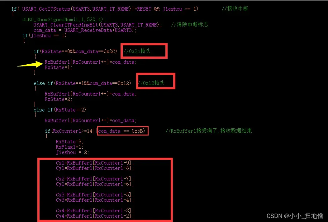
if(RxCounter1>=14||com_data == 0x5B) //RxBuffer1接受满了,接收数据结束
{
RxState=3;
RxFlag1=1;
Jieshou = 2;
Cx1=RxBuffer1[RxCounter1-9];
Cy1=RxBuffer1[RxCounter1-8];
Cx2=RxBuffer1[RxCounter1-7];
Cy2=RxBuffer1[RxCounter1-6];
Cx3=RxBuffer1[RxCounter1-5];
Cy3=RxBuffer1[RxCounter1-4];
Cx4=RxBuffer1[RxCounter1-3];
Cy4=RxBuffer1[RxCounter1-2];
OLED_ShowSignedNum(1,1,Cx1,4);
OLED_ShowSignedNum(2,1,Cy1,4);
OLED_ShowSignedNum(3,1,Cx2,4);
OLED_ShowSignedNum(4,1,Cy2,4);
OLED_ShowSignedNum(1,7,Cx3,4);
OLED_ShowSignedNum(2,7,Cy3,4);
OLED_ShowSignedNum(3,7,Cx4,4);
OLED_ShowSignedNum(4,7,Cy4,4);
}
}
}
else if(RxState==3) //检测是否接受到结束标志
{
if(RxBuffer1[RxCounter1-1] == 0x5B)
{
USART_ITConfig(USART3,USART_IT_RXNE,DISABLE);//关闭DTSABLE中断
if(RxFlag1)
{
AngFlag=0;
HuanRaoZuoBiao();
//
// OLED_ShowSignedNum(1,1,Cx1,4);
// OLED_ShowSignedNum(2,1,Cx2,4);
// OLED_ShowSignedNum(3,1,avel_X1,4);
// OLED_ShowSignedNum(4,1,Cx5[0],4);
AngFlag=1;
RxFlag1 = 0;
RxCounter1 = 0;
RxState = 0;
}
USART_ITConfig(USART3,USART_IT_RXNE,ENABLE);
}
else //接收错误
{
RxState = 0;
RxCounter1=0;
for(i=0;i<10;i++)
{
RxBuffer1[i]=0x00; //将存放数据数组清零
}
}
}
else //接收异常
{
RxState = 0;
RxCounter1=0;
for(i=0;i<10;i++)
{
RxBuffer1[i]=0x00; //将存放数据数组清零
}
}
}
}
注意观察下面这副代码截图:
以上便是我对电赛期间OPENMV与单片机之间实现串口通信的代码实现。学者若有疑问或需要代码工程,可以私聊我。收到后我会及时回复。
版权声明:本文为博主作者:小小_扫地僧原创文章,版权归属原作者,如果侵权,请联系我们删除!
原文链接:https://blog.csdn.net/m0_73931287/article/details/132701860