Packet Tracer – 综合技能练习
地址分配表
|
设备 |
接口 |
IP 地址 |
子网掩码 |
默认网关 |
|
R1 |
G0/0.10 |
172.31.10.1 |
255.255.255.224 |
不适用 |
|
G0/0.20 |
172.31.20.1 |
255.255.255.240 |
不适用 |
|
|
G0/0.30 |
172.31.30.1 |
255.255.255.128 |
不适用 |
|
|
G0/0.40 |
172.31.40.1 |
255.255.255.192 |
不适用 |
|
|
G0/1 |
已分配 DHCP |
已分配 DHCP |
不适用 |
|
|
PC1 |
NIC |
已分配 DHCP |
已分配 DHCP |
已分配 DHCP |
|
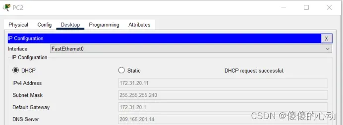
PC2 |
NIC |
已分配 DHCP |
已分配 DHCP |
已分配 DHCP |
|
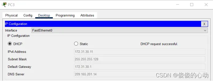
PC3 |
NIC |
已分配 DHCP |
已分配 DHCP |
已分配 DHCP |
|
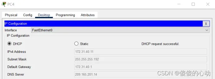
PC4 |
NIC |
已分配 DHCP |
已分配 DHCP |
已分配 DHCP |
VLAN 端口分配和 DHCP 信息
|
端口 |
VLAN 编号 – 名称 |
DHCP 池名称 |
网络 |
|
Fa0/5 – 0/9 |
VLAN 10 – 销售 |
VLAN_10 |
172.31.10.0/27 |
|
Fa0/10 – Fa0/14 |
VLAN 20 – 生产 |
VLAN_20 |
172.31.20.0/28 |
|
Fa0/15 – Fa0/19 |
VLAN 30 – 市场营销 |
VLAN_30 |
172.31.30.0/25 |
|
Fa0/20 – Fa0/24 |
VLAN 40 – HR |
VLAN_40 |
172.31.40.0/26 |
拓扑图
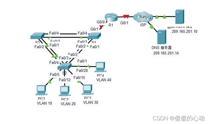
场景
在本总结练习中,您将配置 VLAN、中继、DHCP 服务器、DHCP 中继代理,并将路由器配置为 DHCP 客户端。
要求
使用上表中的信息,执行以下要求:
· 在 S2 上创建 VLAN,并将 VLAN 分配到相应的端口。 名称区分大小写
vlan 10
name Sales
vlan 20
name Production
vlan 30
name Marketing
vlan 40
name HR
· 配置用于中继的 S2 端口。
interface range f0/1-4
switchport mode trunk
· 将 S2 上的所有非中继端口配置为接入端口。
interface range f0/5-9
switchport mode access
switchport access vlan 10
interface range f0/10-14
switchport mode access
switchport access vlan 20
interface range f0/15-19
switchport mode access
switchport access vlan 30
interface range f0/20-24
switchport mode access
switchport access vlan 40
· 配置R1 在 VLAN 之间路由。 子接口名称应与 VLAN 编号对应。
interface g0/0
no shutdown
interface g0/0.10
encapsulation dot1Q 10
ip address 172.31.10.1 255.255.255.224
interface g0/0.20
encapsulation dot1Q 20
ip address 172.31.20.1 255.255.255.240
interface g0/0.30
encapsulation dot1Q 30
ip address 172.31.30.1 255.255.255.128
interface g0/0.40
encapsulation dot1Q 40
ip address 172.31.40.1 255.255.255.192
· 配置 R1 作为连接到 S2 的 VLAN 的 DHCP 服务器。
– 为每个 VLAN 创建 DHCP 池。 名称区分大小写。
– 为每个池分配相应的地址。
– 配置 DHCP 以提供默认网关地址
– 为每个池配置 DNS 服务器 209.165.201.14。
– 防止各池中的前 10 个地址分配给终端设备。
ip dhcp pool VLAN_10
network 172.31.10.0 255.255.255.224
default-router 172.31.10.1
dns-server 209.165.201.14
exit
ip dhcp pool VLAN_20
network 172.31.20.0 255.255.255.240
default-router 172.31.20.1
dns-server 209.165.201.14
exit
ip dhcp pool VLAN_30
network 172.31.30.0 255.255.255.128
default-router 172.31.30.1
dns-server 209.165.201.14
exit
ip dhcp pool VLAN_40
network 172.31.40.0 255.255.255.192
default-router 172.31.40.1
dns-server 209.165.201.14
exit
ip dhcp excluded-address 172.31.10.1 172.31.10.10
ip dhcp excluded-address 172.31.20.1 172.31.20.10
ip dhcp excluded-address 172.31.30.1 172.31.30.10
ip dhcp excluded-address 172.31.40.1 172.31.40.10
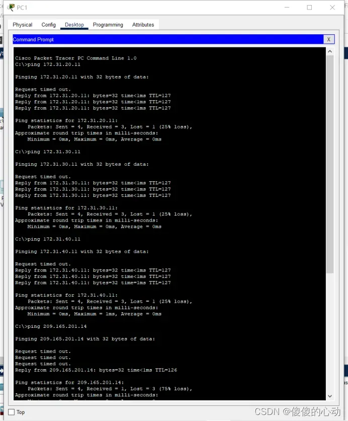
· 验证各 PC 是否具有来自正确 DHCP 池的已分配地址。
注:分配 DHCP 地址可能需要一段时间。 点击加快转发时间加速进程。
· 将 R1 配置为 DHCP 客户端,使其能从 ISP 网络接收 IP 地址。
interface g0/1
ip address dhcp
no shutdown
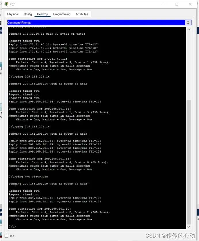
· 验证所有设备现在是否可以互相 ping 并可 ping www.cisco.pka。
【实验过程】
//S2
S2>enable
S2#conf t
Enter configuration commands, one per line. End with CNTL/Z.
S2(config)#vlan 10
S2(config-vlan)#name Sales
S2(config-vlan)#vlan 20
S2(config-vlan)#name Production
S2(config-vlan)#vlan 30
S2(config-vlan)#name Marketing
S2(config-vlan)#vlan 40
S2(config-vlan)#name HR
S2(config-vlan)#exit
S2(config)#interface range f0/5-9
S2(config-if-range)#switchport mode access
S2(config-if-range)#switchport access vlan 10
S2(config-if-range)#interface range f0/10-14
S2(config-if-range)#switchport mode access
S2(config-if-range)#switchport access vlan 20
S2(config-if-range)#interface range f0/15-19
S2(config-if-range)#switchport mode access
S2(config-if-range)#switchport access vlan 30
S2(config-if-range)#interface range f0/20-24
S2(config-if-range)#switchport mode access
S2(config-if-range)#switchport access vlan 40
S2(config-if-range)#exit
S2(config)#interface range f0/1-4
S2(config-if-range)#switchport mode trunk
S2(config-if-range)#end
S2#wr
Building configuration…
[OK]
S2#
//R1
R1>en
R1#conf t
Enter configuration commands, one per line. End with CNTL/Z.
R1(config)#interface g0/0
R1(config-if)#no shutdown
R1(config-if)#
%LINK-5-CHANGED: Interface GigabitEthernet0/0, changed state to up
R1(config-if)#interface g0/0.10
R1(config-subif)#encapsulation dot1Q 10
R1(config-subif)#ip address 172.31.10.1 255.255.255.224
R1(config-subif)#interface g0/0.20
R1(config-subif)#encapsulation dot1Q 20
R1(config-subif)#ip address 172.31.20.1 255.255.255.240
R1(config-subif)#interface g0/0.30
R1(config-subif)#encapsulation dot1Q 30
R1(config-subif)#ip address 172.31.30.1 255.255.255.128
R1(config-subif)#interface g0/0.40
R1(config-subif)#encapsulation dot1Q 40
R1(config-subif)#ip address 172.31.40.1 255.255.255.192
R1(config-subif)#exit
R1(config)#ip dhcp pool VLAN_10
R1(dhcp-config)#network 172.31.10.0 255.255.255.224
R1(dhcp-config)#default-router 172.31.10.1
R1(dhcp-config)#dns-server 209.165.201.14
R1(dhcp-config)#exit
R1(config)#ip dhcp pool VLAN_20
R1(dhcp-config)#network 172.31.20.0 255.255.255.240
R1(dhcp-config)#default-router 172.31.20.1
R1(dhcp-config)#dns-server 209.165.201.14
R1(dhcp-config)#exit
R1(config)#ip dhcp pool VLAN_30
R1(dhcp-config)#network 172.31.30.0 255.255.255.128
R1(dhcp-config)#default-router 172.31.30.1
R1(dhcp-config)#dns-server 209.165.201.14
R1(dhcp-config)#exit
R1(config)#ip dhcp pool VLAN_40
R1(dhcp-config)#network 172.31.40.0 255.255.255.192
R1(dhcp-config)#default-router 172.31.40.1
R1(dhcp-config)#dns-server 209.165.201.14
R1(dhcp-config)#exit
R1(config)#ip dhcp excluded-address 172.31.10.1 172.31.10.10
R1(config)#ip dhcp excluded-address 172.31.20.1 172.31.20.10
R1(config)#ip dhcp excluded-address 172.31.30.1 172.31.30.10
R1(config)#ip dhcp excluded-address 172.31.40.1 172.31.40.10
R1(config)#interface g0/1
R1(config-if)#ip address dhcp
R1(config-if)#no shutdown
R1(config-if)#exit
R1(config)#end
R1#
%SYS-5-CONFIG_I: Configured from console by console
R1#wr
Building configuration…
[OK]
R1#
//PC1~PC4
【实验脚本】
//S2
enable

conf t

vlan 10

name Sales

vlan 20

name Production

vlan 30

name Marketing

vlan 40

name HR

exit

interface range f0/5-9

switchport mode access

switchport access vlan 10

interface range f0/10-14

switchport mode access

switchport access vlan 20

interface range f0/15-19

switchport mode access

switchport access vlan 30

interface range f0/20-24

switchport mode access

switchport access vlan 40

exit

interface range f0/1-4

switchport mode trunk

end

wr
//R1
en

conf t

interface g0/0

no shutdown

interface g0/0.10

encapsulation dot1Q 10

ip address 172.31.10.1 255.255.255.224

interface g0/0.20

encapsulation dot1Q 20

ip address 172.31.20.1 255.255.255.240

interface g0/0.30

encapsulation dot1Q 30

ip address 172.31.30.1 255.255.255.128

interface g0/0.40

encapsulation dot1Q 40

ip address 172.31.40.1 255.255.255.192

exit

ip dhcp pool VLAN_10

network 172.31.10.0 255.255.255.224

default-router 172.31.10.1

dns-server 209.165.201.14

exit

ip dhcp pool VLAN_20

network 172.31.20.0 255.255.255.240

default-router 172.31.20.1

dns-server 209.165.201.14

exit

ip dhcp pool VLAN_30

network 172.31.30.0 255.255.255.128

default-router 172.31.30.1

dns-server 209.165.201.14

exit

ip dhcp pool VLAN_40

network 172.31.40.0 255.255.255.192

default-router 172.31.40.1

dns-server 209.165.201.14

exit

ip dhcp excluded-address 172.31.10.1 172.31.10.10

ip dhcp excluded-address 172.31.20.1 172.31.20.10

ip dhcp excluded-address 172.31.30.1 172.31.30.10

ip dhcp excluded-address 172.31.40.1 172.31.40.10

interface g0/1

ip address dhcp

no shutdown

exit

end

wr
【实验验证】
【实验链接】
链接:https://pan.baidu.com/s/1ioK9SIHmnPo5_z0bTWsSVg?pwd=8312
提取码:8312
–来自百度网盘超级会员V3的分享
【实验知识点】
以下是实验涉及的知识点的详细罗列:
- VLAN(虚拟局域网):在网络设备上创建虚拟局域网,并将每个VLAN分配给相应的端口。
- 中继(Trunk)端口:在交换机上配置用于连接不同VLAN的中继端口,以允许VLAN之间的通信。
- 接入(Access)端口:将交换机上的非中继端口配置为接入端口,使其只属于指定的VLAN。
- 802.1Q封装:在路由器接口上配置子接口,并使用802.1Q封装来将数据帧标记为特定的VLAN。
- IP地址和子网掩码:为每个子接口分配IP地址和相应的子网掩码,以使路由器能够在不同的VLAN之间进行路由。
- DHCP服务器和池:为每个VLAN配置DHCP服务器,并为每个池分配相应的网络地址范围。
- 默认网关:为每个VLAN的DHCP池配置默认网关地址,使客户端能够访问其他网络。
- DNS服务器:为每个DHCP池配置DNS服务器地址,以提供域名解析服务。
- 排除地址:为防止地址冲突或保留特定地址,配置排除地址范围,确保不将这些地址分配给终端设备。
- DHCP客户端:将路由器配置为DHCP客户端,以从ISP网络接收动态分配的IP地址。
- 验证连通性:使用ping命令验证设备之间的连通性,确保各设备能够相互通信。
- 实验脚本编写:根据实验要求,编写适当的命令脚本,以便快速配置设备。
请注意,上述知识点涉及到网络设备的配置和管理,以及基本的网络连接和通信概念。熟悉这些知识点对于进行网络配置和故障排除非常重要。
在实验中,每个错误都是一次宝贵的教训,坚持不懈,你将迎来突破的曙光。
版权声明:本文为博主作者:傻傻的心动原创文章,版权归属原作者,如果侵权,请联系我们删除!
原文链接:https://blog.csdn.net/m0_63624418/article/details/131351909